A couple of years ago I picked-up a small mill for the purpose of creating circuit boards at home. I've "sent out" for boards before, but often I want to prototype something before committing to a design or I only want one and most mail-order services require some minimum number of boards. Also, I just want the capability on-site at the lab, and making my own circuit boards is something I've always wanted to do.
I sunk a lot of time and effort into this at the time, but it didn't go well, and at one point I managed to carve a big chunk out of the router by cutting too deep and decided I was too frustrated to keep working with it.
At the end of last year as we were working to clean-up the lab I saw the machine again and decided it needed to earn the space it's using if it wants to stick-around. I had a few extra hours the other morning and gave it another shot.
The first step was to see if in the intervening years someone else had done the work for me. Sure enough, someone did. mattwach created a wonderful piece of documentation that not only uses the same machine I'm working with, but also in the way that I want to go about it; using all open-source tooling to make basic circuit boards.
This guide got me through most of the process. The majority of the problems came from the typical issue of outdated software and "dependency issues", broken relationships between the various pieces of software (including the computer's operating system). Since the guide does such a good job I'll stick to focusing on the things that didn't go well, but don't let that discourage you if you're considering giving this a shot.
To make a circuit board this way consists of three separate steps (typically with three different pieces of software), each with a specific output:
1. Designing the board and exporting "gerbers"
2. Converting the gerbers to gcode the mill can understand
3. Feeding the gcode to the mill
The first time I attempted this I worked this list in the order above and tried to automate as much as possible. This went OK until it all went to hell when I started trying to do the actual milling. Because of the order I did things in, it wasn't clear at which stage the problems were introduced, so this time around I started at the end of the list so I could have more confidence that each stage is working properly before trying to make them all work together.
Candle
I started by making sure I could control the mill using the Candle software prescribed by the guide. This went fairly smooth, I cloned the repository and followed the instructions in the README to install the necessary tools and dependencies and then compiled the project. The result was a single executable file which ran without complaint on the first try. All that was needed to activate the mill was to open the Service -> Settings menu and select the correct serial port.
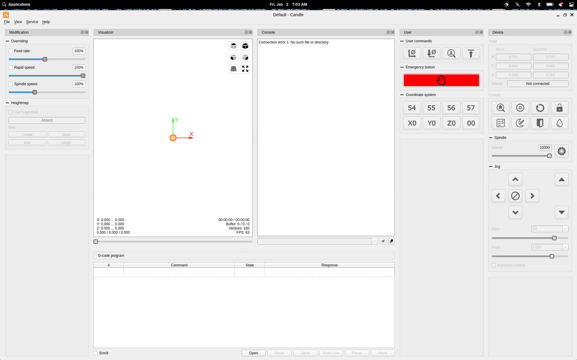
From here I was able to operate the mill's axis manually to make sure everything was still working, and I was even able to load one of the old gcode files from my previous attempt and run the mill using this file (with no tool mounted of course).
At this point I ran through the steps in the guide to set the mill up for "probing" (I used a pair of alligator clip jumper wires to connect to the PROBE inputs on the mill's controller board) and run through the process of generating a heightmap.
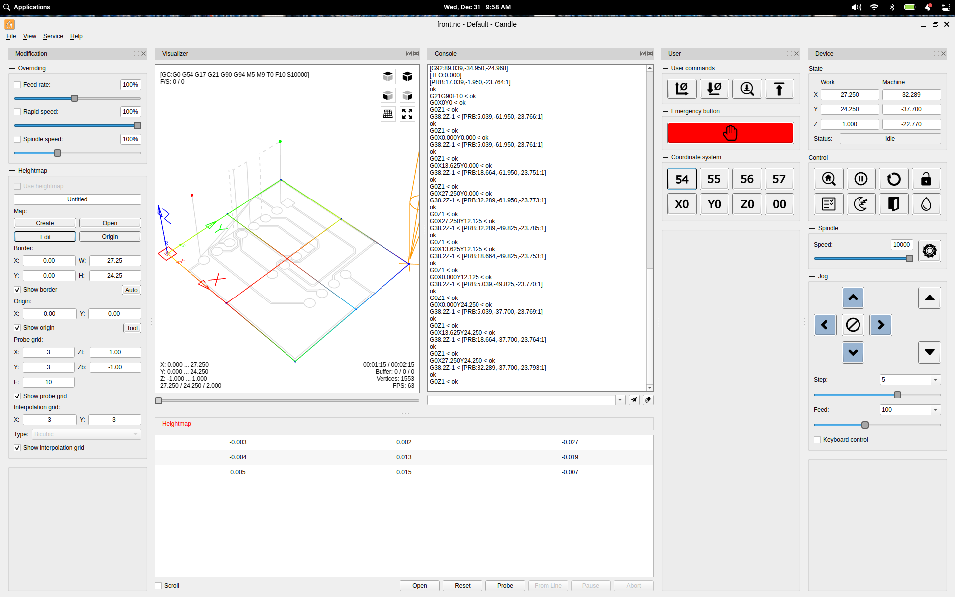
It was extremely tempting at this point to try and mill something, but reflecting on the trouble I had the last time I tried this, I stuck to the plan and started working on the next step.
FlatCAM
When I noticed that Flatcam is written in Python, I knew I was in for a hard time. Python is a cool language, but it has cultivated a serious "dependency hell" over the last decade or two and it's exponentially worse when it comes to software with a graphical interface. I won't bore you with the play-by-play of what it took for me to make this work, I'll just give you the recipe.
First, don't use the version linked from the guide or from the FlatCAM website, it won't work on a modern Linux system. Instead get FlatCAM from this repository:
Once you've cloned that repository, change to it's directory and use the following to start installing the dependencies:
git clone https://github.com/mikelachaine/flatcam-2025.git
cd flatcam-2025
./setup_ubuntu.sh
This will eventually fail, but before we get into that, run this to setup a virtual environment because Python is hell:
python3 -m venv ~/flatcam-2025
source ~/flatcam-2025/bin/activate
pip3 install -r requirements.txt
Now back to installing dependencies:
sudo apt install libcairo2-dev pkg-config python3-dev
pip3 install --force-reinstall --no-cache-dir pycairo
pip3 install -r requirements.txt
pip3 uninstall numpy
pip3 install "numpy<2.0"
Now more weird shit to run it:
export LC_ALL=en_US.UTF-8
export LANG=en_US.UTF-8
python3 FlatCAM.py
This got FlatCAM running and worked until I discovered a bug that caused it to crash when trying to use the Cutout tool. To fix this you need to make a change to the code, so open up flatcam-2025/appGUI/GUIElements.py and change line 1520 to look like this:

This stopped the crashing.
I'm sure there's a more concise way to do all this, but right now I'm focused on making it work, not making it good or easy or... whatever. The next step is to open some gerbers and follow the steps in the guide, so it's time to move-on to the final/first step and make some gerbers.
KiCAD
I could have used an existing KiCAD project for this, but I wanted to refresh my memory from when I was using KiCAD regularly because if I'm able to make boards at home, I'll be using KiCAD more. I wanted something simple in case I had to debug things so I used the Getting Started in KiCAD tutorial to create a design with three parts and when I got to the part about generating gerbers I switched back to the guide.
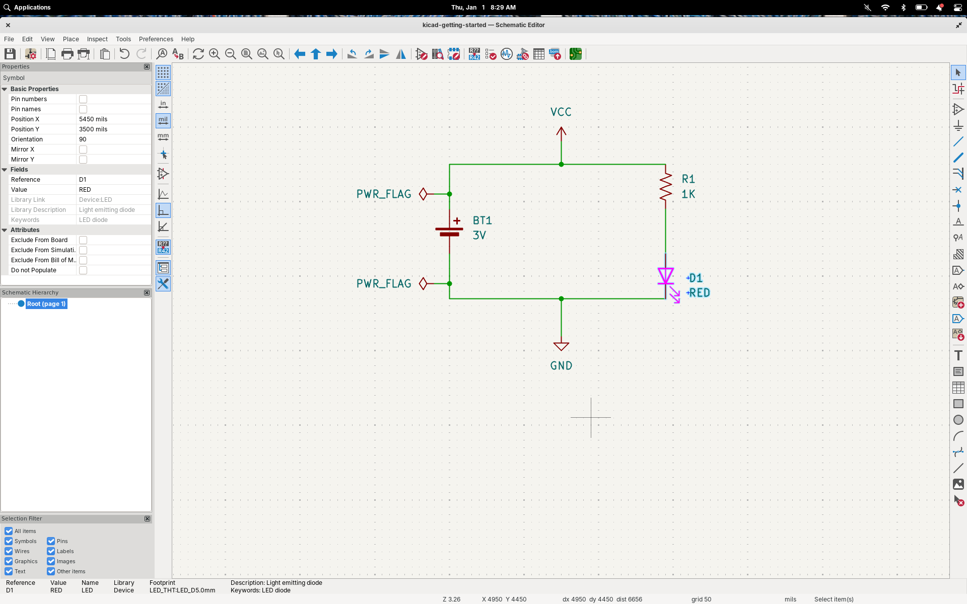
Here there were few surprises other than some options that have been moved/changed since the version of KiCAD shown in the guide, but I set what I could set and exported the files.
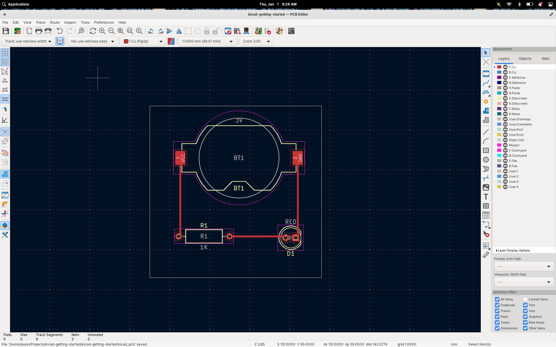
Once I had some gerbers to work with it was time to go back to Flatcad. Again, I followed the guide and there were no surprises. Flatcad spit-out three gcode files to match the three gerbers and it was time to switch-over to Candle.
I went through the setup process again and generated a new heightmap after loading the F.CU layer gcode to make sure it was accurate for the new design and also just to help memorize the process. Again, the guide covers this well and after double-checking everything (don't forget to remove the probing wire from the spindle!), it was time to run the first job.
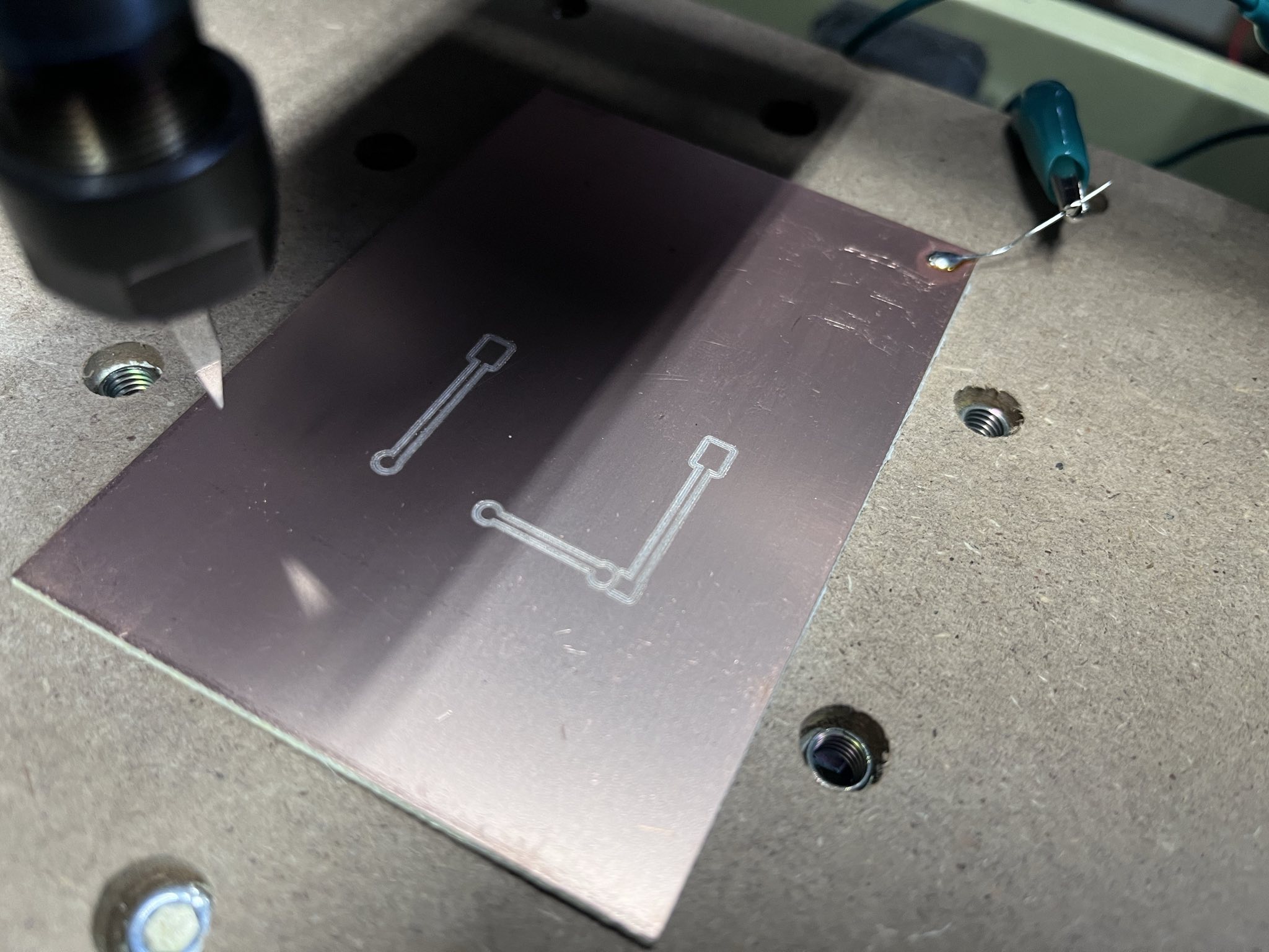
After a few minutes it was done, and the results look good!
I repeated the process for the remaining gcode files, changing the engraving bit for a drill and then an endmill. I re-probed the Z axis with each tool change but used the same heightmap but otherwise did little more than run each file through.
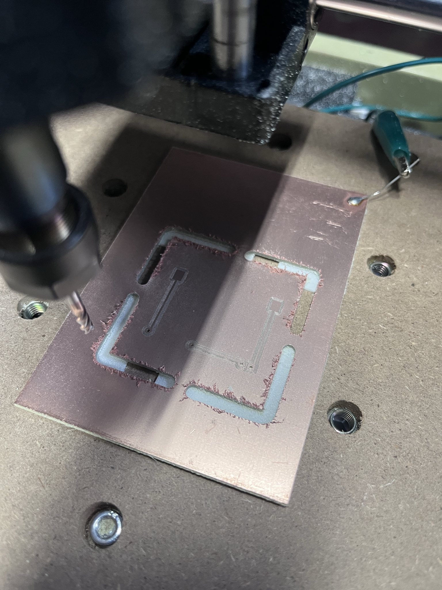
The results were pretty good, but there's certainly room for improvement. It made a lot of noise during the cut-out step and left a pretty rough edge, so I think I might slow-down the movements for that and maybe switch to a smaller endmill. The other thing I noticed is that the isolation cuts left copper in-between which means they are either too narrow or too far apart (maybe the bit just needs to go a little deeper?). In any event nothing that a little tuning shouldn't address.
Even with it's deficits I thought it would be fun to solder it up and see if it works. The parts fit perfect and while it was a little different from soldering a two-sided board with plated holes, it went OK. Unfortunately it didn't work, but my guess is that this was due to the isolation not being perfect and my soldering job causing some kind of short.
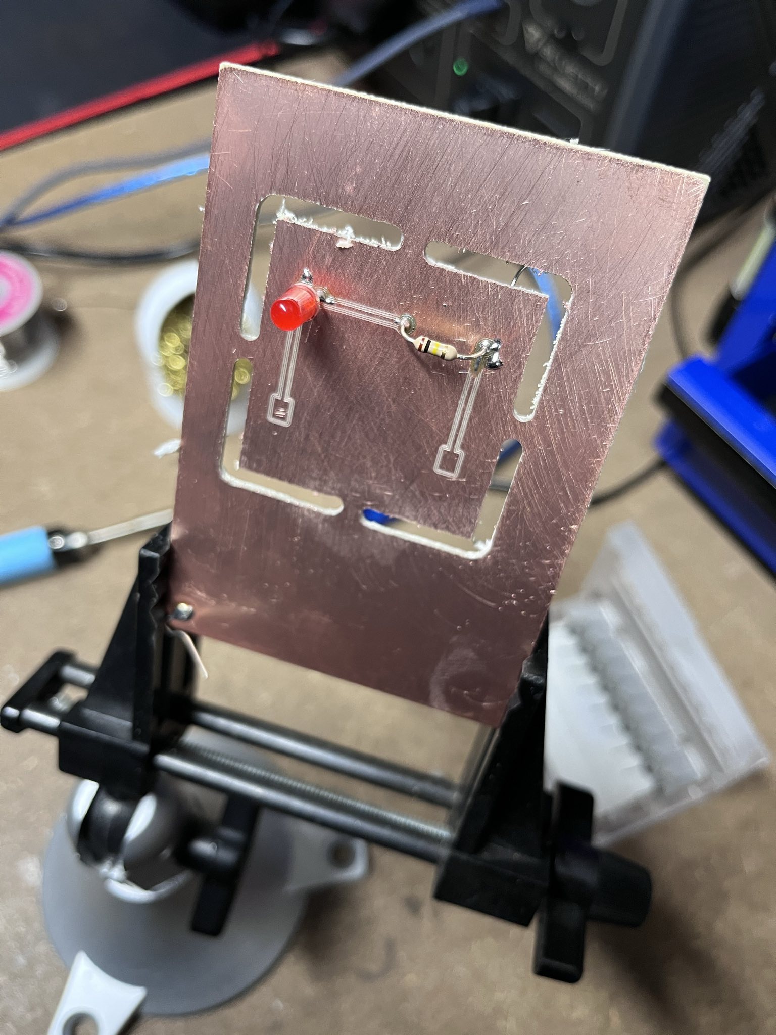
Overall I'm thrilled. I now have a repeatable process that produces usable boards, and I can easily iterate on it to improve the quality of the output. I would like to simplify the workflow but I think I'm going to use it as-is to produce something a little more complex to see if that reveals problems with the flow or limits to what I can make using this process. Once I understand it's capabilities I can try to refine it, but I don't want to do that prematurely and make it harder to figure out where things are going wrong.
Jason J. Gullickson, 2006